Scriber v2.1 Source code download page
Scriber Evaluation PCB
This versatile pcb (75x25mm) may be built in three different ways depending upon the desired use :-
option 1 > A simple stand alone Hellschreiber beacon generating a repeating stored message.
option 2 > A PC or Tablet USB controlled Hellschreiber sender.
option 3 > A full Audio and USB Hellschreiber interface.
The PIC16f1615 microcontroller is preloaded with SCRIBER V2.x software (currently v2.1). This version of Scriber has a UART polarity serial interface (idle=5v) and requires a USB to TTL module for the serial interface to a PC or Tablet. Additionally, the analogue interface levels are changed to suit a MAX9814 agc microphone amplifier module ( 1.25v bias, 0v to midrail span). Otherwise, the software is the same as version 1.0, please refer to the Scriber v1.0 page for a full description of the software.

Scriber Eval v2.0 – Recommended Parts List
R1 10K 0.25w Resistor (see note 1 below)
R2 47R 0.25w Resistor
R3 47R 0.25w Resistor
R4 1K5 0.25w Resistor (see note 1 below)
R5 1K5 0.25w Resistor
RV1 10K horizontal preset 5mm x 10mm pinout or 16mm 10K lin variable pot with pcb tags
RV2 10K horizontal preset 5mm x 10mm pinout or 16mm 10K lin variable pot with pcb tags
RV3 4K7 horizontal preset 5mm x 10mm pinout
C1 22n polyester capacitor 5mm lead spacing
C2 22n polyester capacitor 5mm lead spacing (see note 1 below)
C3 100n polyester capacitor 5mm lead spacing
C4 100n polyester capacitor 5mm lead spacing
C5 100uF 10v electrolytic capacitor 2.5mm lead spacing
IC1 PIC 16F1615 14pin DIL blown with Scriber v2.0 or latter software
Q1 BS170 TO92 N channel switching Mosfet
D1 3 or 5mm low current (2mA) LED
Additional items required dependent on intended use :-
Serial Adaptor – USB to TTL (UART) serial adaptor (ebay or amazon)
– to provide 5volt power and serial communications to the onboard UART
Microphone Module – MAX9814 agc mic amp – Adafruit or similar (ebay or amazon)
SW1 & SW2 – 2 single pole toggle switches for Beacon and Invert functions.
SW3 – 1 single pole push button for Reset/Abort
Header pins or sockets – 0.1 inch, single row type
Note 1 – If the audio interface is to be used (Option 3 build), these filter components value should be used to increase the HF response to 3KHz :-
R1 4K7
R4 470R
C2 100n
Build up

- Fit C4 & C5 Supply decouplers, the values are not particularly critical
- Fit the IC1, ensure it’s the right way round and observe static precautions.
- Fit RV1 & RV2, either presets or 16mm linear pots, any value from 5k to 50k is fine.
- Fit R2 & R3, these are current limiters and may be any value to suit the application
- Fit R5 & D1, usually the longer leg on D1 is +ve but this is not always the case – check it
At this point Scribers basic functions can be checked, apply a 5volt supply to J5, the supply current should be around 5mA.
Turn both presets fully clockwise and momentarily short pin1 (B) of J2 to 0v, the TX LED should light for around 20 seconds whilst Scriber sends it’s beacon message. If you’ve a scope, pin 2 of J3 (PWM) will have 31.25KHz PWM on it & pin 4 of J4 will have ‘digital’ sinewaves whilst the beacon is active.
If all’s well the rest of the components may be fitted or if only the PWM output is required for optical comms none of the rest of the components need be fitted.
Connecting the USB

A USB to serial TTL (uart) adapter is required, search Ebay or Amazon for ‘USB to TTL adapter’. I suggest to only get ones that use either the FTDI FT232 chip or Silicon labs CP2102 chip as the drivers required are readily available on these companies web sites. (note – do not use USB to RS232 (9pin) adapters, these have the wrong signal polarity and may damage Scriber)
- Download and install a serial terminal program – ‘Termite‘ is very good and easy to use.
- Go to the chip manufacturers website, download and install the correct driver for the device fitted to the adapter. (FTDI drivers , Silicon Labs drivers)
- Connect the adapter to the PC via a USB cable and start ‘Termite’, if all is well you should have a new COM port listed.
- Select the new com port and set it to 9600 baud, 8bit, 1 stop & no parity.
- In Termite’s settings – select ‘append CR’ and deselect ‘local echo’.
- Fit a jumper link between TXD & RXD pins on the adapter to test remote loop back.
In Termite, type something on the bottom line, press enter and if everything is OK, the text will echo back in the box above.
Now to connect the adapter to Scriber —
- Remove the jumper and connect the 0v & 5v outputs on the adapter to the corresponding pins on J5 of Scriber.
- Connect the TXD pin on the adapter to J5 pin 2 on Scriber
- Connect the RXD pin on the adapter to J5 pin 3 on Scriber
Plug the adapter into the USB and reset Scriber (momentarily short pin 3 of J2 to 0v), You should then get Scriber’s welcome message and a prompt on screen.
Download and install SPECTRAN , connect Scriber mic output (J1 pin 3) to the mic input of a PC, enable Scriber’s Beacon (connect J2 pin1 to 0v), Scriber will continuously send it beacon message centred on 800Hz – experiment with Spectran and Scriber’s controls until you are familiar with their effects. ( see Scriber v1.0 for more information ).
Adding a Microphone input
Scriber can also accept a MAX9814 agc microphone amplifier module to provide both voice and hellschreiber output. This may be useful when Scriber’s output is being fed into the Mic socket of a radio or to enable the use of a PC headset.

The MAX9814 chip is available on a tiny module from Amazon, Ebay or Adafruit with an on board electret microphone capsule. The capsule may be removed and an external microphone used. The module provides several gain and compression options. The 20dB AGC range ensures a constant output level.
The module is interfaced to Scriber using J4 on the Evaluation PCB.

Port J4 can also be used to incircuit program the microcontroller, if both uses are required it’s best to use a plug and socket arrangement.
Scriber has an internal 300Hz to 3KHz digital bandpass filter with hf pre-emphasis optimized for speech. An external PTT line is used to select voice transmission.
Lightwave modulation using Scriber
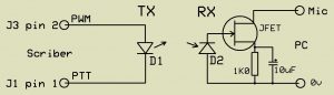
Apart from its normal use via an SSB radio, Scriber makes an excellent modulator for Lightwave communication. The very simple circuit above uses LED’s for both TX and RX. The TX LED (D1) is connected between Scribers PWM output and the PPT line, R3 (47ohm) on the Scriber PCB sets the LED current at 60mA pk.
D2 is an LED of the same type and is used as a photodetector, a JFET (J310, MPF102 or similar) forms a buffer from the very high impedance of the LED to the Microphone input of a PC running Spectran. The PC mic input provided the low voltage DC bias for the FET.
Different LED’s will give widely varying results, the best I’ve found are TruOpto 5mm Red LED’s rated at 100,000mcd with a 15 degree beam width, available from Rapid Electronics, order code 56-0420. A pair of these will give >30m range with no additional optics even in daylight .
The very simple circuit above gives surprisingly good performance and leaves plenty of room to experiment with lens etc. for much greater ranges. Far more capable designs and in depth information on optical communications can be found on G8AGN & KA7OEI’s web pages.

Scriber v2.0 PCB pin descriptions
There are 5 single row 0.1 inch pitch connectors positions labled J1 to J5 on the PCB, they may be populated with either pins or sockets and may be fitted either side of the PCB to suit the application. All the connectors are on a 0.1 grid for easy use as a daughter board in a larger project.
J1 – Radio:
pin 1 – PTT, active low to during transmission, can safely sink 300mA and withstand 30volts
pin 2 – 0 volt
pin 3 – transmit audio output, upto 500mV pk to pk from the 4k7 Level preset
J2 – Switches:
pin 1 – Beacon, connect to 0v to select beacon mode
pin 2 – Invert, connect to 0v to send inverted text
pin 3 – Reset, connect to 0v to reset microcontroller
pin 4 – 0 volt
J3 – Aux:
pin 1 – 0 volt
pin 2 – PWM, digital output befor the filter, may be used to drive an LED or PIN switch, max current 100mA
pin 3 – TX, active high during transmission, may be used to drive an opto isolator, max current 100mA
J4 – Data and Power – connect to a USB to TTL adaptor for both 5v power and serial data, UART polarity ie. idle = high
pin 1 – +5v power, <10mA + any current drawn from J3.
pin 2 – RXD, 9600 baud, serial data input to Scriber’s UART
pin 3 – TXD, 9600 baud, serial data output from Scriber’s UART
pin 4 – 0 volt
J5 – Program – Microcontroller programing port, one to one connection to Microchip’s PicKit 3. When not being used to
program the chip this may be used as an analogue interface with the following pin functions.
It may be connected directed to Maxim’s MAX9814 agc’ed microphone amplifier chip.
pin 1 – MCLR, microcontroller reset, active low
pin 2 – 5v power in or out
pin 3 – 0 volt
pin 4 – Audio output, Hi-z 5v p-p DAC audio monitor
pin 5 – Audio input, from the output of the MAX9814 module
pin 6 – External PTT switch to 0v for speech transmission
note – The analogue interface must be disconnected during in-circuit programing .