
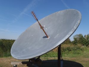
My experimental receive only 23cm EME setup.
The Dish is 1.7 m with an F/D of 0.35 and a novel bifilar backfire helix feed (more on that below).
LNA – G4DDK design followed by a 3 pole interdigital filter
RX – Fun Cube Dongle
Software – HDSDR and MAP65
Sun noise – consistently measures between 7 & 8 dB , Moon noise is undetectable.
The Backfire Helix Feed
Many of the high performance feed designs for 23cm have relatively large diameters, often between 30 and 40cm. This is a significant aperture blockage when used with small prime focus dishes (my 1.7m dish is near the minimum size usable). Especially when you consider that this blockage occurs in the centre of the beam with a -12 dB edge illumination.
I couldn’t find any good small circular polarized feed designs until I came across this declassified US defence paper written by Willard Patton in 1962, PDF Here
Ignoring the maths, the polar diagrams suggested that the backfire helix would make an very good dish feed – Broad bandwidth (ie. dimensionally uncritical), sharp beam cutoff, controllable beamwidth, good front to back ratio and very low blockage – 0nly 7cm diameter.
Paul Wade, W1GHZ, in his excellent paper on Helical dish feeds Here gives a couple of examples of Backfire Helix feeds, also suggesting good performance .
Since neither of the above gave any actual designs some experimentation was going to be necessary…..
The backfire helix is a traveling wave antenna (ie. non resonant) and therefore, a wide bandwidth (+/- 30%). It may be implemented with one or more inter wound ‘arms’. The simplest monofilar version requires a small ground plane (<0.3 wave lengths diameter) and gives an axially offset radiation cone, but is the easiest to construct and feed. The bifilar variant is axially aligned, does not need a ground plane but requires a balance drive.
Before I go any further, it has to be said that the Helix feed does have one major problem – there seems to be no way to obtain both LH and RH circular polarization from a single feed , not a problem for a receive only system but I shall need both polarization’s for an EME transceiver.
Also, being an unscreened structure with a wide frequency response, it is more susceptible to off frequency terrestrial signals, especially 900MHz mobile phones, a good interdigital filter is advisable after the LNA, especially if the receiver has poor filtering/dynamic range (ie RTL’s & Funcube’s).
Intuitive theory of operation
Consider a bifilar wound helix of several turns with a circumference of one wavelength, the two arms being fed at one end with a balanced RF drive. It may be thought of as having two regions – the unbounded region being the first half turn of the arms after the feed point and the bounded region being the remainder of the helix.
In the bounded region every point on the axis of the helix has an adjacent turn both before and after it. At the operating frequency, the RF will be in phase at all adjacent points, ie. there is no potential difference between adjacent turns and therefor no incentive for current to flow. thus, this region acts as an RF choke, the far end being ‘RF dead’.
In the unbounded region near the feed points the situation is different, Having an ‘in phase’ adjacent turn on only one side, it radiates freely a broad cone of circularly polarized radiation in the direction of the point of feed.
In practice the transition between the two regions is not abrupt but a progressive exponential decay of the RF current (and therefor the radiation) after the first half turn. This progressive decay sharpens the cutoff of the radiation cone, minimizing overspill and side lobe radiation. 4 turns being sufficient to ensure proper operation, increasing the number of turns further, provides only marginal improvement in side and back lobe reduction.
The beam width may be optimized by changing the pitch of the helix, reducing the pitch will narrow the beam. Backfire helix feeds are best suited to deep dishes with F/D’s between 0.3 and 0.4 .
Construction and Matching
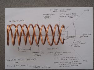
The helix was formed from 3/16 inch (4.8mm o/d) copper brake pipe, (ebay in 10m roll) on a 68mm former (UK guttering down pipe). The central support is 15mm copper water pipe. The feed point is a 40mm disk of 1.6mm FR4 pcb material which can slide on the 15mm tube. This allows the pitch of the helix to be altered to suit the dish during final setup. The helix arms were flattened at the feed end and drilled with 3mm holes to enable them to be bolted to the PCB disk. The dead end may be a short or open circuit or even used to a feed dc bias to the LNA.
The Bifilar Helix requires a balanced drive estimated to be around 200 to 300 ohm impedance. Thus a 4:1 balun was used to provide a moderate match to 50ohm RG402 semi rigid coax, measure at -15dB return loss. The half wave section is 80mm of RG402 bent in a hairpin with the outer soldered at both ends to the ground plane on the 40mm disk. Experiments with a 1/4 wave matching section (the brass tube in the first picture) didn’t improve the match.
It is also possible to make the helix from RG402, feed the RF in at the cold end, down one of the arms and simply put a break in the outer at the fed point. Thus using the Helix itself as an infinite balun. This was not tried as one arm is about a metre long and would have a loss of around 0.4dB @ 23cm in RG402.
Final adjustment of the pitch of the helix (beam width) was done on the dish with a dipole probe 1/4 wave above the dish surface to obtain -12dB edge illumination.
It was noted by Patton (1st reference above) that placing tubes of surprisingly large diameter inside the helix had little effect on it’s performance, I also found this to be true, thus there is the possibility of placing the pre-amp right at the fed point or perhaps a second feed for a higher band ( 3 cm horn for Es’hail2).
Footnote – A fine pitch backfire helix should also make a good ‘exciter’ for a circularly polarized loop yagi, I have not tried this.
Feedback & Questions welcome via the Contact pull down
————————————————————————
For the future
The current system is a simple receive only 1.7m dish, I’m hoping to achieve a full transceive system on the large 3.6 m dish here and to experiment with EME Hellschreiber in the future.
My experiments with 2 counter wound helix, one inside the other, to achieve TX/RX showed this to be not possible. The inter reaction completely destroyed the beam patterns. I am considering a mechanical (pneumatic operated) end over end change over between a TX & RX Helix which holds the possibility of eliminating the change over relay and would allow separate optimization for maximum gain on the TX and best G/T for the RX.
The Es’hail 2 geostationary satellite due for launch in late 2017/early 2018 will carry a 13 cm to 3 cm transponder and should be workable using quite modest power levels (<10 watts) and a < 90cm dish. A suitable dual band dish feed is required. A backfire helix could provide the circular polarized TX feed on 13cm and would allow a 3 cm RX feedhorn to be mounted internally without interfering with the operation of the helix – just a thought.
Some results – ARI eme contest 24/25th Sept 2016 heard on 23cm JT65C :-
DC9UP, DK0ZAB, DK3WG, G4CCH, G4FUF, I0NAA, I1NDP, IK3COJ, IK5VLS, NC1I, OK2DL, PA3FXB, RA3EC, SP5GDM
ON0EME beacon peaks at 10 dB above noise in 6Hz RBW – just audible