18th Feb 2019
Update > Es’hail ( now designated Q0100 ) is active so it became possible to verify the correct winding sense for the helix — So all the photo’s below have the WRONG sense, the helix needs to be wound the same direction as a normal right hand threaded bolt. I’ll update all the photo’s in the near future (too busy experimenting with the satellite just now).
28/01/2019
13cm TX Backfire Helix Dish Feed for Es’hail 2 uplink
At the time of writing Es’hail 2 is in the commissioning phase and has generated a lot of interest in 10GHz reception of the satellite using standard TV dishes and PLL controlled LNB’s. The low cost of the RX side and the modest dish sizes required suggests a 2 dish solution as a simple option for full transceive operation, eliminating all the problems of a dual band dish feed and enabling live monitoring of one’s own transmissions through Es’hail.

Described below is the construction of a 2.4GHz circular polarized feed suitable for a prime focus dish with an f/D ratio in the range 0.3 and 0.4 .
This feed is a 13cm version of my 23cm EME feed but using a simpler quarter wave 3 wire balun to feed the helix.
It is a bifilar wound backfire helix, it’s operation is quite different from the more commonly known forward firing helix which uses a rear reflector. The circular polarized RF is the opposite hand to a conventional helix and is a broad cone ( around 150 degrees) of illumination emanating from the 1st half turn after the feed point in the direction of the SMA connector. Thus the feed may be conveniently mounted on a protrusion from the centre of the dish with a coax feed from the rear. For more information on the backfire helix please look at my 23cm EME Helix feed page.
Construction
The feed uses only simple junk box items and can be easily constructed in less than a hour, hopefully the method is self evident from the photo’s and notes below :-
Materials required :-
1/ 120cm of 32 amp ‘twin and earth’ UK house wiring cable (solid core, 1.8mm conductor)
2/ SMA socket, I used the PCB mounting type as it has substantial ‘legs’ but any type will work
3/ 12cm of 36mm outside diameter plastic pipe ( UK sink waste pipe, for solvent welding)

Winding the Helix
Cut a 12cm piece of 36mm pipe and file two diametrically opposite 5mm deep slots in each end to secure the wire.
Cut a 1.2 metre length of ’32 amp twin and earth’, straighten it out and slit down the centre with a shape knife and extract one of the cores.
Locate the centre of the wire and place across a pair of slots at one end of the former. Close wind under tension, both ends together (bifilar style) in a ‘left hand thread’ direction. ** See update at the bottom of the page **
Grab the last 2 turns and stretch the winding down the former. Pull each wire under tension into its slot and bend inwards to secure. You should end up with 4 turns of each arm and short equal tails.
Secure the winding temporarily with tape or a ty-wrap and space the winding out evenly on the former.
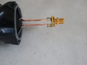
Bend the 2 tails outward with a sharp bend and bare back as per the above picture.
Making the Balun
Bend the tails perfectly straight and parallel with a 4mm air gap. Cut the parallel section to a length of 29mm measured from the start of the 1st bend.
Note :- These two dimensions are fairly critical to get the Balun centered on 2.4GHz.
Butt the two tails against the inside face of the SMA socket and solder to the earth tags, taking care to preserve the two critical dimensions.

Make up a centre conductor from the same wire and solder in place. The exact length is not particularly critical but centralization is, I found it useful to slide two short pieces of silicon rubber sleeving on the centre conductor and cut them off after soldering. A clothes peg helped to keep it all straight.

The former may now be removed if required, pull the top (far end) wire out of it’s slots and bend it aside to allow extraction.
Note – the plastic former does not affect the electrical performance or VSWR of the feed and may be left in place if required.
Set-up
The helix winding itself is very broadband (+/-30%) and therefore dimensionally uncritical, it has little effect on the VSWR. The balun is relatively narrow band and critical to obtaining a good match at 2.4GHz. The 2:1 VSWR bandwidth of the balun is around 300MHz. If the critical balun dimensions have been achieved the feed should have a better than 2:1 VSWR without adjustment, however since this type of ‘wire’ construction isn’t very exact, I do strongly recommend checking/setting the VSWR using test equipment.

The above photo was taken after careful adjustment of the balun using a spectrum analyser and tracking generator + directional coupler and shows a better than 20dB return loss at 2.40GHz ( 5dB/div vertical, sweep from 2 to 3 GHz).
In the ‘as built’ state, the frequency of best VSWR will be off and require adjustment. Bending the two arms of the balun apart where it joins the helix by one or two millimetres will increase the frequency of the ‘null’ by up to 200MHz and may be used as a fine adjustment. If the null error is too great the length of all 3 conductors should be shortened to increase the frequency. This obviously requires the SMA to be unsoldered thus it’s best to carry out these tests before removing the coil former. Tuning rate is approximately 100MHz per millimetre.
Using the above method, a 15dB return loss (1.5:1) or better should be readily obtainable.

On the Dish
The feed will need to be weather proofed. The balun section in particular must be kept clean and dry, any dielectric material (heatshrink,epoxy etc) placed on the balun will greatly upset the VSWR. The best solution is to enclose the entire feed within a 50mm sealed plastic pipe which also can form a convenient mounting rod. This will not affect the RF performance.
As built, the feed is optimal for f/D = 0.35 Dishes, for deeper dishes, increasing the pitch of the helix will broaden the illumination cone. The focus of the dish should be set to the junction between the balun and the helix – see my 23cm EME Helix feed page for more details.
IMPORTANT – Helix winding sense, LH or RH ?
The feed has been extensively bench tested (6 prototypes) but since Es’Hail has yet to fire up, there may be a few changes to this page before I can finalize the design.
Descriptions given relating winding sense to left and right hand circular are often ambiguous, I am not certain I have the winding sense correct for the helix shown above and suggest waiting till it can be confirmed on air or perhaps build both a RH and a LH version, with a bit of practice it only takes 30 minutes to make one.
Hope to see you on Es’hail soon, 73’s …….Graham, G8HAJ
——————— Additional information added 30/1/2019 ———
Measurements
I do not have a proper RF test range and it’s far too cold to do the measurements outside, however the following may at least give an indicator of performance :-
Transmission tests :-
Gain – a pair of feeds were compared to a pair of dipoles at the same separation, the feeds giving around 5 dB more signal. Thus the feed has a gain of around +2.5dBd (or 4.5dBi).
Circularity – One feed was axially rotated through 360 deg relative to the other, no significant variation in signal strength was seen, ie. there was no nulling and the level remained constant within 1dB, ie. the polarization circularity appears to be good.
Beamwidth tests :-
hard to measure accurately in a reflective environment, however the following estimates were obtained by stretching / compressing the helix to different lengths :-
helix length – 7cm, -6dB beamwidth of around 140 deg ( good for f/D rations 0.35 to 0.4)
helix length – 10cm, -6dB beamwidth of around 160 deg (good for f/D rations 0.3 to 0.35)
helix length – 13cm, -6dB beamwidth of around 180 deg (good for f/D ratios 0.25 (focal plane dishes) to 0.3)
-6dB in beamwidth corresponds to a -10dB edge illumination (max gain) since there is an additional -4dB spreading loss to the edge at these low f/D ratios.
It was not possible to obtain any reliable indication of side/back lobe levels due to signal reflections in the room.
Important – Winding sense update
After posting details on the Amsat-dl forum, I received the very useful suggestion from Remco PA3FYM, that since my 23cm helix works well for EME receive which is LHCP and it is LH tread wound , Es’hail, which requires RHCP, should be right hand thread wound (obvious really – just didn’t think of it). So it appears all the above photos have the wrong winding sense and a right hand thread wound helix should be correct for Es’hail – Thanks Remco.